Commercial Pool and Spa Supplies
Link Automation, Legacy (100 & 1000 Series) Rotary Flow Switch
Link Automation, Legacy (100 & 1000 Series) Rotary Flow Switch
SKU:LINK-FSOLD
Couldn't load pickup availability
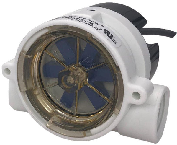
The Link Automation Legacy Rotary Flow Switch (100 & 1000 Series) (Pool Link / Link Automation) is an electro-mechanical safety interlock and visual circulation monitor engineered for legacy Pool Link commercial automation controllers. Installed directly in the sample bypass flow stream adjacent to the probe manifold, it serves as the primary fail-safe mechanism: it continuously verifies water movement across analytical electrodes and mechanically signals the controller to lock out chemical feed outputs (chlorine/bromine feeders, acid pumps, $CO_2$ solenoids) if pool circulation halts or bypass flow drops below operating thresholds.
Hardware Architecture & Operational Mechanics
Engineered for continuous exposure to high-velocity chlorinated, brominated, and chemically treated pool water:
-
Dual-Action Functionality: Combines a local visual spinning indicator with an automated electrical interlock in a single compact housing.
-
Rotary Impeller / Paddle Assembly: A chemical-resistant polymer paddle wheel (rotor) suspended on low-friction bearing pins (typically titanium, ceramic, or 316 stainless steel) sits directly in the sample channel. Incoming flow spins the rotor, offering immediate visual confirmation of water flow without requiring an external flowmeter.
-
Magnetic Reed Switch Interlock: An encapsulated rare-earth magnet embedded in one or more rotor blades sweeps past an externally mounted, hermetically sealed reed switch once or several times per revolution. Depending on the legacy controller revision:
-
Pulsed / Frequency Detection: Sends continuous micro-pulses to the 100/1000 Series motherboard; the controller interprets pulse frequency to confirm active flow.
-
Centrifugal / Magnetic Latch Contact: A steady closure dry contact maintained only while rotor angular velocity exceeds the trip threshold.
-
-
Fail-Safe De-Energized State: If the pump turns off, a pre-filter strainer clogs, or bypass valves close, rotor movement ceases immediately. The reed contact opens, placing the controller in a "NO FLOW" alarm state and de-energizing chemical feed relays within seconds to prevent hazardous gas accumulation in piping loops.
-
Corrosion-Resistant Enclosure: Constructed with an optical-grade acrylic or clear polycarbonate viewing barrel seated on a chemical-resistant PVC, PVDF, or polypropylene base.
Technical Specifications
-
Compatible Controller Series: Pool Link / Link Automation 100 Series and 1000 Series commercial chemical automation systems.
-
Electrical Contact Rating:
-
Sealed SPST Form A dry contact reed switch.
-
Rated for low-voltage signal loops: Max 24V AC/DC, 0.5A resistive load.
-
Direct 2-conductor cable lead to the controller's dedicated
FLOWterminal strip.
-
-
Actuation Flow Range:
-
Cut-In (Flow OK): Typically actuates at 0.4 to 0.6 GPM (approx. 1.5 to 2.3 LPM).
-
Cut-Out (No Flow): Drops out below 0.3 GPM (approx. 1.1 LPM).
-
-
Maximum Working Pressure: 50 PSI (approx. 3.45 bar), matching standard acrylic manifold pressure limits.
-
Operating Water Temperature: 32°F to 120°F (0°C to 49°C).
-
Plumbing Interfaces: Standard 1/4" NPT or 1/2" NPT female ports, commonly adapted to 3/8" OD compression tube fittings for standard bypass poly tubing.
-
Cable Lead: Standard 6-foot to 10-foot (approx. 1.8 to 3.0 m) factory-jacketed 2-conductor unshielded or shielded low-voltage lead.
Maintenance & Diagnostic Testing
-
Common Failure Modes:
-
Mechanical Jamming: Hair, lint, or calcium carbonate scale lodging between the paddle blades and the chamber wall, preventing rotation despite normal bypass flow.
-
Bearing Pin Wear: Long-term mechanical erosion causing the rotor to wobble and scrape the inner chamber.
-
Reed Switch Contact Failure: Welded or stuck open contacts caused by electrical spikes or lightning surges.
-
-
Routine Cleaning Protocol: Annually (or during seasonal startup), isolate the bypass loop, unthread the clear viewing cap or body union, extract the paddle rotor, and soak it in a 5% to 10% muriatic acid solution for 5 minutes to dissolve calcification. Inspect bearing tips for grooves or flat spots before reassembly.
-
Electrical Continuity Test: Using a digital multimeter set to continuity/resistance ($\Omega$):
-
Disconnect the two switch leads from the controller terminal strip.
-
With flow off, verify the circuit reads Open Loop ($OL$).
-
Restore bypass flow and confirm the paddle spins freely. Verify the meter reads near 0 $\Omega$ (or emits steady intermittent continuity beeps if configured for pulse mode).
-
Disconnect main AC power to the legacy 1000 Series controller enclosure. Close the bypass supply and return isolation valves to relieve hydraulic pressure in the probe manifold.
Verification: Pressure gauge on the manifold reads 0 PSI and the controller display is unpowered.
Disconnect the two temperature sensor wires from the controller's mainboard terminal strip (noting polarity/terminal designations). Unscrew the sensor probe from the acrylic manifold port counter-clockwise using an open-end wrench.
Verification: Port threads are clean and free of remnants from old Teflon tape or cracked plastic.
Apply 2 to 3 wraps of PTFE thread sealing tape to the new sensor's male NPT threads. Hand-tighten into the flow cell port and snug an additional 1 turn with a wrench. Route the cable into the low-voltage knock-out and secure the leads into the temperature terminals.
Verification: Sensor is seated firmly without leaking under line pressure, and wire terminals are clamped tight.
Restore AC power to the controller and open bypass isolation valves. Compare the controller's displayed water temperature against an independent calibrated handheld thermometer or photometer reading taken at the petcock.
Verification: Displayed temperature stabilizes and tracks within $\pm 1^\circ\text{F}$ of the reference thermometer.