Commercial Pool and Spa Supplies
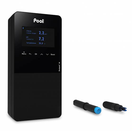
Pool Link 500 Series, Amperometric FAC PPM Probe (0-20ppm)
Pool Link 500 Series, Amperometric FAC PPM Probe (0-20ppm)
SKU:LINK-FACPPM
Couldn't load pickup availability
The Pool Link 500 Series Amperometric Free Available Chlorine (FAC) PPM Probe (0–20 PPM) (Pool Link / Link Automation) is a commercial-grade electrochemical sensor designed for continuous, direct quantification of free chlorine residual in commercial aquatic facilities, waterparks, splash pads, and municipal pools.
Operating on amperometric principles, it measures the electrical current generated by the reduction of hypochlorous acid ($\text{HOCl}$) and hypochlorite ions ($\text{OCl}^-$) at a working electrode surface, providing real-time concentration readouts in parts-per-million ($\text{PPM}$ or $\text{mg/L}$) independent of cyanuric acid interference. The expanded 0–20 PPM range accommodates high-demand recreational water venues requiring elevated disinfectant thresholds or automated shock/breakpoint chlorination tracking.
Hardware & Analytical Architecture
Engineered for continuous immersion in dynamic bypass flow loops across high-turnover natatorium and waterpark environments:
-
Micro-Porous Membrane Assembly: Utilizes a replaceable, electrolyte-filled membrane cap (typically microporous PTFE, PVDF, or composite polymer). The selective membrane allows dissolved hypochlorous acid molecules to diffuse through to the internal electrode while preventing bather organics, oils, suspended solids, and scale from coating the working electrode surface.
-
Working & Counter/Reference Electrode Pair: Features an internal gold ($\text{Au}$) or platinum ($\text{Pt}$) working cathode where chemical reduction occurs, paired with a silver/silver chloride ($\text{Ag/AgCl}$) reference anode in a specialized, pre-buffered internal gel electrolyte reservoir.
-
Expanded Dynamic Range (0–20.00 PPM): Calibrated to maintain linearity well beyond standard recreational bands ($1.0–5.0\text{ PPM}$), allowing uninterrupted monitoring through secondary shock dosing, waterpark wave pools, and hyper-chlorinated municipal splash pads.
-
Signal Conditioning Electronics: Houses an encapsulated internal pre-amplifier that converts low nanoampere-level reduction currents into a stable, low-noise analog voltage or digital signal transmitted directly to the Pool Link 501 controller board.
-
Flow-Dependent Diffusion Chamber: Designed specifically to mount inside the Pool Link 500 Series machined acrylic bypass flow cell manifold, ensuring consistent laminar flow velocity across the membrane face.
Technical Specifications
-
Measurement Range: 0.00 to 20.00 PPM (mg/L) Free Available Chlorine (FAC).
-
Resolution: 0.01 PPM ($0.00–9.99\text{ PPM}$); 0.1 PPM ($10.0–20.0\text{ PPM}$).
-
Operating pH Dependency: Operates optimally between pH 6.80 and 8.00 (calibrated via the controller's integrated pH sensor for automated hypochlorous acid dissociation curve compensation).
-
Linearity & Accuracy: $\pm 2\%$ of full scale or $\pm 0.05\text{ PPM}$ (whichever is greater) under stable flow and temperature.
-
Response Time ($T_{90}$): Typically reaches $90\%$ of reading within 15 to 30 seconds after sample chlorine concentration shifts.
-
Sample Stream Flow Requirements: Requires a constant bypass velocity of 0.5 to 1.5 GPM (approx. 1.9 to 5.7 LPM) within the acrylic flow cell to prevent sample starvation at the membrane boundary.
-
Operating Temperature Range: 35°F to 120°F (2°C to 49°C).
-
Maximum Hydraulic Pressure: 50 PSI (approx. 3.45 bar) in closed acrylic flow manifolds.
-
Process Fitting: 1" or 3/4" NPT threaded body / compression collar gland mount matched to the Pool Link 500 Series multi-port acrylic chamber.
-
Cable Configuration: Standard 10-foot (approx. 3.0 m) factory-shielded, low-noise multi-conductor lead (terminated with a keyed CONX water-tight circular plug or labeled PCB terminal pins).
Commissioning, Calibration & Electrolyte Maintenance
         Bypass Flow In (Laminar, 0.5–1.5 GPM)
                         │
                         ▼
        ┌───────────────────────────────────┐
        │       Probe Body / Pre-Amp        │
        │  ┌─────────────────────────────┐  │
        │  │ Internal Buffer Electrolyte │  │
        │  │       (Ag/AgCl Anode)       │  │
        │  └──────────────┬──────────────┘  │
        │                 │                 │
        │          Working Cathode          │
        │         (Gold / Platinum)         │
        └─────────────────┬─────────────────┘
                          ▼
            [ Selective Membrane Cap ]
                          ▲
                          │
          Continuous Diffusion of HOCl/OCl⁻
-
Polarization Period (Burn-In): When newly installed or refilled with fresh electrolyte, the probe requires 1 to 2 hours of continuous electrical polarization under steady bypass flow before zero-point and span calibration can occur.
-
Zero & Span Calibration:
-
Zero Reference: Calibrated in dechlorinated water (or by using the controller's software zero offset).
-
Span Calibration: Performed using a calibrated primary colorimeter or DPD-1 photometer test taken directly from the petcock sampling valve while the pool is at normal operational setpoint ($2.0–5.0\text{ PPM}$).
-
-
Electrolyte & Membrane Replacement Interval: The internal gel electrolyte and membrane cap should be serviced every 6 to 12 months, or sooner if response times become sluggish or readings drift erratic due to calcification or bio-film fouling.
Disconnect main AC power to the legacy 1000 Series controller enclosure. Close the bypass supply and return isolation valves to relieve hydraulic pressure in the probe manifold.
Verification: Pressure gauge on the manifold reads 0 PSI and the controller display is unpowered.
Disconnect the two temperature sensor wires from the controller's mainboard terminal strip (noting polarity/terminal designations). Unscrew the sensor probe from the acrylic manifold port counter-clockwise using an open-end wrench.
Verification: Port threads are clean and free of remnants from old Teflon tape or cracked plastic.
Apply 2 to 3 wraps of PTFE thread sealing tape to the new sensor's male NPT threads. Hand-tighten into the flow cell port and snug an additional 1 turn with a wrench. Route the cable into the low-voltage knock-out and secure the leads into the temperature terminals.
Verification: Sensor is seated firmly without leaking under line pressure, and wire terminals are clamped tight.
Restore AC power to the controller and open bypass isolation valves. Compare the controller's displayed water temperature against an independent calibrated handheld thermometer or photometer reading taken at the petcock.
Verification: Displayed temperature stabilizes and tracks within $\pm 1^\circ\text{F}$ of the reference thermometer.