Commercial Pool and Spa Supplies
Pool Link 500 Series, Amperometric TAC PPM Probe (0-20ppm)
Pool Link 500 Series, Amperometric TAC PPM Probe (0-20ppm)
SKU:LINK-TACPPM
Couldn't load pickup availability
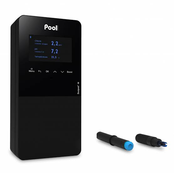
The Pool Link 500 Series Amperometric Total Available Chlorine (TAC) PPM Probe (0–20 PPM) (Pool Link / Link Automation) is a specialized commercial-grade electrochemical sensor engineered for continuous, real-time quantification of Total Chlorine residual in municipal aquatic facilities, indoor competitive natatoriums, waterparks, and commercial spas.
Unlike Free Available Chlorine (FAC) probes that selectively measure hypochlorous acid ($\text{HOCl}$) and hypochlorite ($\text{OCl}^-$), the TAC probe incorporates an internal catalytic or iodide-supplemented reagent electrolyte behind its microporous membrane. This reaction reduces both free chlorine and combined chlorine species—chloramines such as monochloramine, dichloramine, and nitrogen trichloride—converting them into a measurable reduction current scaled directly to parts-per-million ($\text{PPM}$ or $\text{mg/L}$) Total Chlorine. When paired with a matching 500 Series FAC probe, it allows the controller to compute real-time Combined Chlorine ($\text{TAC} - \text{FAC} = \text{Combined Chlorine}$) to automate UV systems, ozone destruction loops, or breakpoint shock dosing.
Hardware & Analytical Architecture
Engineered for continuous immersion in dynamic bypass flow loops across high-bather-load commercial environments:
-
Catalytic Total Chlorine Reaction Matrix: Employs a specialized membrane-covered electrolyte cell containing a potassium iodide ($\text{KI}$) buffer system. Chloramines and free chlorine diffuse through the membrane and oxidize iodide ions into triiodide ($\text{I}_3^-$), which is electrochemically reduced at the working electrode, generating a current proportional to Total Chlorine concentration.
-
Micro-Porous Polymer Membrane Cap: Features a precision microporous PTFE or PVDF membrane assembly designed to protect the internal working electrode from bather organics, body oils, cyanuric acid, and calcium scale while regulating diffusion rates.
-
Electrode Configuration: Contains a noble metal cathode (typically platinum or gold) where chemical reduction takes place, paired with an integrated silver/silver chloride ($\text{Ag/AgCl}$) reference anode submerged in the buffered electrolyte reservoir.
-
Expanded Dynamic Range (0–20.00 PPM): Broad measurement window covers standard operational ranges ($1.0–5.0\text{ PPM}$) as well as elevated thresholds required for secondary disinfection loops, indoor chloramine management, and automated breakpoint hyper-chlorination cycles.
-
Internal Pre-Amplifier Circuitry: Houses encapsulated signal-conditioning electronics within the upper body, translating nanoampere redox currents into a temperature-compensated, low-noise analog voltage or digital signal for the Pool Link 501 controller.
-
Bypass Cell Compatibility: Direct mechanical fit for the Pool Link 500 Series machined acrylic multi-port bypass flow cell manifold.
Technical Specifications
-
Measurement Parameter: Total Available Chlorine (TAC / Total Residual Chlorine).
-
Measurement Range: 0.00 to 20.00 PPM (mg/L).
-
Resolution: 0.01 PPM ($0.00–9.99\text{ PPM}$); 0.1 PPM ($10.0–20.0\text{ PPM}$).
-
Operating pH Dependency: Operates across pH 6.50 to 8.50 (best performance achieved when paired with the controller's active pH sensor for automatic algorithmic compensation).
-
Linearity & Accuracy: $\pm 2\%$ of full scale or $\pm 0.05\text{ PPM}$ under stable temperature and bypass flow.
-
Response Time ($T_{90}$): Reaches $90\%$ of stabilized value within 60 to 120 seconds (TAC reaction dynamics are slightly slower than direct FAC reduction due to the internal iodide oxidation step).
-
Sample Stream Flow Requirements: Requires a continuous bypass flow of 0.5 to 1.5 GPM (approx. 1.9 to 5.7 LPM) within the acrylic chamber to prevent boundary layer depletion at the membrane surface.
-
Operating Temperature Limits: 35°F to 120°F (2°C to 49°C).
-
Maximum Hydraulic Working Pressure: 50 PSI (approx. 3.45 bar).
-
Process Fitting: 1" or 3/4" NPT external body threads / compression gland mount.
-
Cable Lead: Standard 10-foot (approx. 3.0 m) factory-shielded, chemical-resistant multi-conductor cable terminated with a sealed CONX circular connector or stripped/tinned PCB terminal leads.
Commissioning, Calibration & Electrolyte Maintenance
         Bypass Flow In (Laminar, 0.5–1.5 GPM)
                         │
                         ▼
        ┌───────────────────────────────────┐
        │       Probe Body / Pre-Amp        │
        │  ┌─────────────────────────────┐  │
        │  │ Potassium Iodide Buffer     │  │
        │  │ Electrolyte (Ag/AgCl Anode) │  │
        │  └──────────────┬──────────────┘  │
        │                 │                 │
        │          Working Cathode          │
        │         (Gold / Platinum)         │
        └─────────────────┬─────────────────┘
                          ▼
            [ Selective Membrane Cap ]
                          ▲
                          │
          Continuous Diffusion of HOCl/OCl⁻
               & Combined Chloramines
-
Polarization (Burn-In) Period: Upon initial installation or after electrolyte replenishment, the sensor requires 2 to 4 hours of continuous electrical polarization under steady bypass flow before zero-offset and span calibration can be finalized.
-
Calibration Protocol:
-
Zero Calibration: Set in dechlorinated water or via controller zero-offset adjustment.
-
Span Calibration: Performed using a calibrated primary photometer or colorimeter test (Total Chlorine DPD-3 or DPD-4 reagent test) drawn directly from the probe chamber petcock while the recirculation system operates under normal bather loads.
-
-
Electrolyte & Membrane Replacement: The internal catalytic iodide electrolyte and membrane cap require routine servicing every 3 to 6 months (or sooner under heavy bather and high-chloramine conditions), as internal reagents gradually deplete through continuous chemical consumption.
Disconnect main AC power to the legacy 1000 Series controller enclosure. Close the bypass supply and return isolation valves to relieve hydraulic pressure in the probe manifold.
Verification: Pressure gauge on the manifold reads 0 PSI and the controller display is unpowered.
Disconnect the two temperature sensor wires from the controller's mainboard terminal strip (noting polarity/terminal designations). Unscrew the sensor probe from the acrylic manifold port counter-clockwise using an open-end wrench.
Verification: Port threads are clean and free of remnants from old Teflon tape or cracked plastic.
Apply 2 to 3 wraps of PTFE thread sealing tape to the new sensor's male NPT threads. Hand-tighten into the flow cell port and snug an additional 1 turn with a wrench. Route the cable into the low-voltage knock-out and secure the leads into the temperature terminals.
Verification: Sensor is seated firmly without leaking under line pressure, and wire terminals are clamped tight.
Restore AC power to the controller and open bypass isolation valves. Compare the controller's displayed water temperature against an independent calibrated handheld thermometer or photometer reading taken at the petcock.
Verification: Displayed temperature stabilizes and tracks within $\pm 1^\circ\text{F}$ of the reference thermometer.