Commercial Pool and Spa Supplies
Pool Link 500 Series, Clear Piston Flow Switch (PI)
Pool Link 500 Series, Clear Piston Flow Switch (PI)
SKU:LINK-CPFS
Couldn't load pickup availability
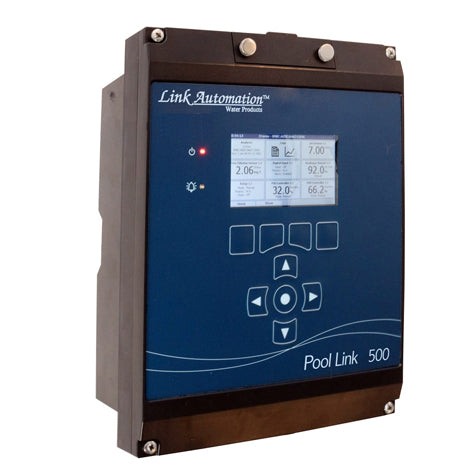
The Pool Link 500 Series Clear Piston Flow Switch (PI) (Pool Link / Link Automation) is a dedicated electro-mechanical safety interlock switch integrated directly into the acrylic bypass flow manifold of the Pool Link 500 and 501 Series commercial water chemistry automation controllers. It combines a transparent sight chamber, a free-floating magnetic piston (shuttle), and an external photo-interrupter/reed interlock mechanism (PI) to provide continuous visual confirmation of water movement while serving as the primary electrical fail-safe to lock out chemical feed outputs when bypass circulation stalls.
Hardware Architecture & Operational Dynamics
Engineered to prevent chemical deadheading and dry-firing in commercial swimming pools, spas, and natatoriums:
-
Clear Optical Sight Cylinder: Precision-machined from cast optical-grade acrylic or heavy-wall polycarbonate. It provides 360° visibility of the internal piston chamber, allowing maintenance technicians to visually confirm flow dynamics, entrained air bubbles, or bio-scaling without taking the bypass loop off-line.
-
Weighted Magnetic Piston / Shuttle: Houses a lightweight, chemical-resistant polymer piston embedded with a permanent ceramic/alnico magnet. Water entering the bottom of the vertical chamber drives the piston upward against gravity and fluid drag.
-
PI Interlock Module: An externally mounted sensor block—configured with a magnetic reed capsule or a solid-state optoelectronic/photo-interrupter (PI) pickup—detects the elevated position of the piston. When flow drops below minimum operating velocity, gravity returns the piston to the bottom seat, breaking the circuit and triggering an immediate controller interlock.
-
Non-Binding Internal Geometry: Features longitudinal bypass grooves or a tapered bore to allow fluid flow around the perimeter of the piston. This prevents hydraulic lockup and reduces sticking caused by hair, lint, or particulate accumulation.
-
Chemical-Grade Materials: Wetted components consist of optical acrylic, PVDF/Delrin piston polymers, and Viton (FKM) elastomeric O-rings, ensuring long-term resistance to liquid chlorine, muriatic acid, cyanuric acid, and ozone off-gas.
Technical Specifications
-
Compatible Controllers: Pool Link 501, Pool Link 500 Series, and Link Automation commercial chemical controllers.
-
Electrical Contact Configuration:
-
Form A SPST dry contact (Normally Open - NO; closes upon verified flow).
-
Max voltage/current rating: 24V AC/DC, 0.5A inductive/resistive load.
-
Direct 2-wire or 3-wire low-voltage interface to the controller motherboard's
FLOWterminal strip.
-
-
Hydraulic Actuation Thresholds:
-
Cut-In (Flow Verified / Contact Closes): Typically 0.40 to 0.60 GPM (approx. 1.5 to 2.3 LPM).
-
Cut-Out (No Flow / Contact Opens): Drops out below 0.25 to 0.35 GPM (approx. 0.95 to 1.3 LPM).
-
-
Maximum Hydraulic Working Pressure: 50 PSI (approx. 3.45 bar), matching standard 500 Series acrylic chamber ratings.
-
Operating Water Temperature: 32°F to 120°F (0°C to 49°C).
-
Process Fitting Connections: Standard 1/4" NPT or 1/2" NPT female inlet and outlet ports (or integrated into the 500 Series acrylic manifold block with 3/8" OD compression tubing fittings).
-
Cable Lead: Standard 10-foot (approx. 3.0 m) factory-jacketed 2-conductor or shielded instrumentation pigtail.
Installation & Alignment Guidelines
-
Mandatory Vertical Orientation: Because the clear piston relies on gravity-assisted return, the switch must be installed vertically with flow moving upward. Installing horizontally or with downward flow prevents proper piston seating and creates a dangerous false "Flow OK" condition.
-
Air Purging: Trapped air bubbles at the top of the sight glass can cushion the piston or cause erratic chatter. Use the manifold's top sample petcock or bleed valve to purge entrained air after initial line filling or filter backwashing.
-
Upstream Debris Protection: While more fouling-resistant than rotary paddle wheels, fine calcification or debris can become trapped between the piston and the acrylic wall. Ensure bypass water is drawn downstream of the facility's main filtration system.
Maintenance & Descaling Procedure
-
Visual Inspection: If the controller displays a persistent "NO FLOW" warning while the main recirculation pump is running, inspect the clear chamber. If the piston is resting at the bottom despite active water flow, it is fouled with calcium scale or debris.
-
Descaling: Isolate the bypass loop using the inlet and outlet needle valves. Unthread the piston chamber barrel, remove the internal piston, and soak both in a 5% to 10% muriatic acid solution or white vinegar for 5 to 10 minutes until bubbling ceases. Rinse thoroughly with fresh water and reassemble. Never scrape the acrylic bore with metallic tools or abrasive scouring pads.
Disconnect main AC power to the legacy 1000 Series controller enclosure. Close the bypass supply and return isolation valves to relieve hydraulic pressure in the probe manifold.
Verification: Pressure gauge on the manifold reads 0 PSI and the controller display is unpowered.
Disconnect the two temperature sensor wires from the controller's mainboard terminal strip (noting polarity/terminal designations). Unscrew the sensor probe from the acrylic manifold port counter-clockwise using an open-end wrench.
Verification: Port threads are clean and free of remnants from old Teflon tape or cracked plastic.
Apply 2 to 3 wraps of PTFE thread sealing tape to the new sensor's male NPT threads. Hand-tighten into the flow cell port and snug an additional 1 turn with a wrench. Route the cable into the low-voltage knock-out and secure the leads into the temperature terminals.
Verification: Sensor is seated firmly without leaking under line pressure, and wire terminals are clamped tight.
Restore AC power to the controller and open bypass isolation valves. Compare the controller's displayed water temperature against an independent calibrated handheld thermometer or photometer reading taken at the petcock.
Verification: Displayed temperature stabilizes and tracks within $\pm 1^\circ\text{F}$ of the reference thermometer.