Commercial Pool and Spa Supplies
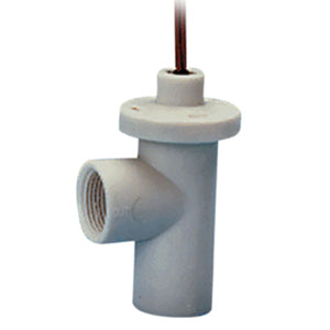
Pool Link 500 Series, Flow Switch (Omega)
Pool Link 500 Series, Flow Switch (Omega)
SKU:LINK-FS
Couldn't load pickup availability
The Pool Link 500 Series Flow Switch (Omega) (Pool Link / Link Automation) is a specialized, high-reliability inline or bypass safety interlock switch manufactured for the Pool Link 500 and 501 Series commercial water chemistry automation controllers. Engineered around an industrial Omega Engineering flow-sensing mechanism (typically a magnetically coupled piston shuttle or low-drag flapper/vane assembly), it serves as the primary system fail-safe, ensuring chemical feed outputs (chlorine/bromine feeders, acid pumps, $CO_2$ solenoids, and electrolytic cells) are locked out if water flow through the analytical bypass manifold ceases.
Hardware Architecture & Sensing Dynamics
Designed to eliminate false flow readings and prevent dry-fire feed conditions in commercial natatoriums, waterparks, and institutional aquatic facilities:
-
Magnetic Reed Interlock Mechanism: Contains a hermetically sealed, gas-filled magnetic reed switch capsule isolated from the wetted water stream. An internal magnet embedded within a spring-biased piston or pivoted vane shifts under dynamic line velocity, actuating the switch contacts once the minimum actuation flow rate is achieved.
-
Non-Rotary, Fouling-Resistant Core: Unlike spinning paddle-wheel or rotary flow switches, the Omega-style shuttle/vane design features no rotating shafts or delicate bearing pins. This linear or pivoted actuation path prevents binding and false "Flow OK" sticking caused by hair, lint, suspended organics, or calcium carbonate scaling in high-load commercial pools.
-
Corrosion-Proof Wetted Components: Wetted internals utilize chemical-grade polymers (such as glass-reinforced Noryl, PVDF, or polypropylene), high-purity ceramic/alnico magnets, and 316 stainless steel or Hastelloy springs to resist degradation from high chlorine residuals, muriatic acid, and saline electrolytic pool water.
-
Direct 500/501 Controller Interface: Transmits a clean dry-contact signal directly to the dedicated low-voltage
FLOWinterlock terminals on the Pool Link 501 mainboard, triggering instant visual/audible alarms and relay shut-offs upon flow interruption.
Technical Specifications
-
Compatible Controller Systems: Pool Link 501, 500 Series, and compatible Link Automation commercial chemical controllers.
-
Switch Contact Configuration:
-
Sealed SPST Form A (Normally Open - NO) dry reed contact.
-
Contact closes on flow increase; opens immediately on flow loss.
-
Rated up to 24V AC/DC, 0.5A maximum switching current.
-
-
Hydraulic Actuation Parameters:
-
Actuation Flow Rate (Cut-In): Typically 0.50 to 0.75 GPM (approx. 1.9 to 2.8 LPM) in bypass configurations.
-
De-Actuation Flow Rate (Cut-Out): Typically 0.30 to 0.40 GPM (approx. 1.1 to 1.5 LPM).
-
-
Maximum Hydraulic Working Pressure: 50 PSI (approx. 3.45 bar) in acrylic bypass chambers; up to 100 PSI (approx. 6.89 bar) in direct inline pipe configurations.
-
Operating Water Temperature: 32°F to 140°F (0°C to 60°C).
-
Process Plumbing Connection: Standard 1/2" NPT or 3/4" NPT male/female threaded ports (or 1/4" NPT adapters for direct mounting into Pool Link 500 Series acrylic manifolds).
-
Electrical Lead: Standard 10-foot (approx. 3.0 m) 2-conductor shielded or PVC-jacketed low-voltage pigtail lead.
Installation & Alignment Best Practices
-
Flow Orientation: Ensure the directional flow arrow stamped onto the switch body aligns with actual bypass water movement. Installing the unit reversed will prevent the internal shuttle or flapper from engaging the magnetic reed contact.
-
Mounting Attitude: In low-velocity bypass loops, mount vertically with flow moving upward (or horizontally if spring-assisted). Vertical-upward mounting leverages both spring return and gravity to ensure clean de-actuation when circulation drops.
-
Pre-Filtration: To prevent particulate wedging, ensure the bypass stream draws from a point downstream of the pool's primary filtration media, or install an inline cleanable mesh strainer (80 to 100 mesh) upstream of the switch.
Disconnect main AC power to the legacy 1000 Series controller enclosure. Close the bypass supply and return isolation valves to relieve hydraulic pressure in the probe manifold.
Verification: Pressure gauge on the manifold reads 0 PSI and the controller display is unpowered.
Disconnect the two temperature sensor wires from the controller's mainboard terminal strip (noting polarity/terminal designations). Unscrew the sensor probe from the acrylic manifold port counter-clockwise using an open-end wrench.
Verification: Port threads are clean and free of remnants from old Teflon tape or cracked plastic.
Apply 2 to 3 wraps of PTFE thread sealing tape to the new sensor's male NPT threads. Hand-tighten into the flow cell port and snug an additional 1 turn with a wrench. Route the cable into the low-voltage knock-out and secure the leads into the temperature terminals.
Verification: Sensor is seated firmly without leaking under line pressure, and wire terminals are clamped tight.
Restore AC power to the controller and open bypass isolation valves. Compare the controller's displayed water temperature against an independent calibrated handheld thermometer or photometer reading taken at the petcock.
Verification: Displayed temperature stabilizes and tracks within $\pm 1^\circ\text{F}$ of the reference thermometer.