Commercial Pool and Spa Supplies
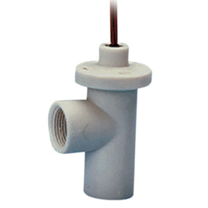
Pool Link 500 Series, In Line Flow Switch (Gems)
Pool Link 500 Series, In Line Flow Switch (Gems)
SKU:LINK-FS
Couldn't load pickup availability
The Pool Link 500 Series In-Line Flow Switch (Gems) (Pool Link / Link Automation) is a commercial-grade, inline magnetic shuttle safety interlock switch engineered for Pool Link 500 and 501 Series automation controllers. Manufactured around an industrial Gems Sensors liquid flow-switch platform, it installs directly in the primary sample bypass loop or feed line. It acts as a dedicated electrical interlock to immediately disable all chemical feed outputs (chlorine/bromine feeders, acid metering pumps, and $CO_2$ solenoid valves) the instant water circulation falls below critical operating thresholds.
Hardware Architecture & Operational Dynamics
Engineered for reliable, continuous operation in chemically aggressive mechanical rooms:
-
Hermetically Sealed Reed Capsule: The electrical switching element is completely isolated from the wetted water passage within an external non-magnetic chamber. A high-reliability Form A reed switch actuates via magnetic coupling, preventing water contact, chemical attack, or pin oxidation.
-
Internal Magnetic Shuttle / Piston: Water entering the switch displaces an internal spring-loaded or gravity-biased magnetic piston. When flow reaches the set actuation velocity, the internal magnet aligns with the reed switch to close the circuit. When flow drops, the return mechanism pulls the shuttle back, breaking the circuit instantly.
-
Fouling-Resistant In-Line Design: Unlike paddle-wheel or flapper designs, the Gems inline shuttle has no rotating pins, exposed hinges, or flexible vanes that can become tangled with hair, lint, or debris from high-bather-load commercial pools.
-
Chemical-Grade Polymer or Brass/316 SS Body: Typically molded from glass-reinforced Noryl, Ryton (PPS), or machined brass/stainless steel with fluorocarbon (Viton) or EPDM dynamic seals, providing high resistance to liquid chlorine, muriatic acid, and ozone off-gassing.
-
Controller Interface: Supplies a dry contact closure directly to the low-voltage
FLOWterminals on the Pool Link 501 mainboard, signaling a fail-safe shutdown within seconds of flow loss.
Technical Specifications
-
Compatible Systems: Pool Link 501, Pool Link 500 Series, and Link Automation commercial controllers.
-
Switch Contact Configuration:
-
Sealed SPST Form A dry contact (Normally Open - NO under zero flow).
-
Contact closes on flow increase; opens on flow loss.
-
Electrical rating: Up to 24V AC/DC, 0.5A to 1.0A maximum switching current.
-
-
Flow Actuation Parameters:
-
Cut-In (Flow Switch Closes): Typically 0.50 to 0.75 GPM (approx. 1.9 to 2.8 LPM).
-
Cut-Out (Flow Switch Opens): Typically 0.30 to 0.40 GPM (approx. 1.1 to 1.5 LPM).
-
-
Maximum Working Pressure: Up to 100 PSI (approx. 6.89 bar) in rigid pipe runs; rated to 50 PSI (approx. 3.45 bar) when integrated into acrylic bypass loops.
-
Operating Water Temperature: 32°F to 140°F (0°C to 60°C).
-
Plumbing Interfaces: Standard 1/2" NPT or 3/4" NPT female/male threads (often adapted to 3/8" OD compression fittings for flexible bypass tubing).
-
Electrical Lead: Standard 10-foot (approx. 3.0 m) 2-conductor shielded or PVC-jacketed 18–22 AWG instrumentation cable.
Installation & Alignment Guidelines
-
Flow Orientation: Pay strict attention to the directional flow arrow molded or stamped on the Gems switch body. Reverse installation prevents the shuttle from moving toward the reed contact, resulting in a permanent "NO FLOW" condition.
-
Mounting Attitude: Best installed in a vertical pipe run with flow moving upward. This orientation utilizes both gravity and spring tension for clean, rapid shuttle return when circulation stops. If mounted horizontally, ensure the electrical housing sits upright and verify the model is equipped with a positive spring return.
-
Upstream Clearance: To prevent turbulence from causing shuttle chatter, provide at least 5 pipe diameters of straight, unobstructed pipe upstream of the switch inlet.
Disconnect main AC power to the legacy 1000 Series controller enclosure. Close the bypass supply and return isolation valves to relieve hydraulic pressure in the probe manifold.
Verification: Pressure gauge on the manifold reads 0 PSI and the controller display is unpowered.
Disconnect the two temperature sensor wires from the controller's mainboard terminal strip (noting polarity/terminal designations). Unscrew the sensor probe from the acrylic manifold port counter-clockwise using an open-end wrench.
Verification: Port threads are clean and free of remnants from old Teflon tape or cracked plastic.
Apply 2 to 3 wraps of PTFE thread sealing tape to the new sensor's male NPT threads. Hand-tighten into the flow cell port and snug an additional 1 turn with a wrench. Route the cable into the low-voltage knock-out and secure the leads into the temperature terminals.
Verification: Sensor is seated firmly without leaking under line pressure, and wire terminals are clamped tight.
Restore AC power to the controller and open bypass isolation valves. Compare the controller's displayed water temperature against an independent calibrated handheld thermometer or photometer reading taken at the petcock.
Verification: Displayed temperature stabilizes and tracks within $\pm 1^\circ\text{F}$ of the reference thermometer.