Commercial Pool and Spa Supplies
Pool Link 500 Series, Probe Connector
Pool Link 500 Series, Probe Connector
SKU:LINK-TINNED
Couldn't load pickup availability
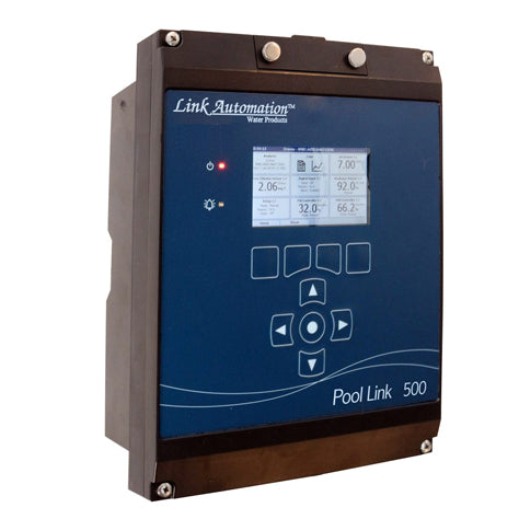
The Pool Link 500 Series Probe Connector (Pool Link / Link Automation) refers to the specialized electrical interface fittings used to terminate, bulkhead-mount, and couple analytical sensors (pH, platinum/gold ORP, temperature, and amperometric FAC/TAC probes) to the Pool Link 501 and 500 Series commercial controller enclosures.
Depending on the hardware revision and environment specifications, the 500 Series utilizes two primary connector architectures: the traditional BNC Bulkhead/Plug System for cost-effective standard service, and the water-tight, quick-disconnect CONX Industrial Circular Connector System designed for high-humidity, corrosive mechanical room environments.
Hardware Architecture & Connector Variants
1. CONX Industrial Circular Bulkhead & Cable Connector
-
Sealed IP67 / NEMA 6P Construction: Designed to provide a submersible-grade, gas-tight barrier against ambient chloramine vapors, muriatic acid fumes, and washdown spray.
-
Positive Locking Mechanism: Employs a circular multi-pin layout with a threaded collar or quarter-turn bayonet locking ring and internal fluorocarbon/nitrile elastomeric O-rings to prevent accidental disconnects and pin oxidation.
-
Keyed Shell Alignment: Mechanical indexing grooves prevent inverted pin alignment and reverse-polarity faults during probe swaps in dark or tight chemical rooms.
-
Internal Pin Configuration: Available in 2-pin (standard ORP/temp), 3-pin/4-pin (shielded analog combinations), and multi-pin configurations for integrated pre-amplifiers or digital amperometric signals.
2. Isolated BNC Bulkhead Jack & Male Plug
-
RF/Coaxial Design: Precision-machined brass body with bright nickel plating or gold-flashed contact pins to minimize junction resistance.
-
Ground Isolation Washers: Chassis-mount BNC jacks on the 500 Series controller enclosure incorporate non-conductive nylon/Teflon isolation shoulder washers. This keeps the signal reference ground floating and completely isolated from the metallic enclosure or earth ground, eliminating 60 Hz AC ground loops and erratic millivolt drift.
-
Elastomeric Weather Boot: Male cable ends feature molded silicone or EPDM boots to shield the bayonet coupling mechanism from atmospheric moisture.
Technical Specifications
-
Impedance Rating: Low-noise 50 $\Omega$ or 75 $\Omega$ matched impedance across low-voltage analytical bands.
-
Contact Resistance: $< 5\text{ m}\Omega$ initial contact resistance across pins/sockets.
-
Insulation Resistance: $> 1,000\text{ M}\Omega$ at 500V DC (critical for high-impedance pH glass electrode circuits exceeding $10^8\ \Omega$).
-
Operating Voltage Rating: Up to 30V AC/DC (standard analytical operating potential $\pm 2,000\text{ mV DC}$).
-
Operating Temperature Limits: -4°F to 158°F (-20°C to 70°C).
-
Enclosure Knockout Fitment: Standard 1/2" (approx. 0.84" / 21.3 mm) or 5/8" industrial chassis hole patterns for enclosure panel glands.
-
Cable Strain Relief: Integral compression chuck or overmolded bend-relief boot accommodating 0.150" to 0.250" OD instrumentation cabling.
Installation & Maintenance Guidelines
-
Enclosure Bulkhead Isolation: When replacing a chassis-mount BNC connector, always confirm that both inner and outer nylon isolation shoulder washers are seated correctly. If the metal shell of the BNC makes direct contact with a grounded metal controller chassis, the pH and ORP readings will drift uncontrollably or peg at full scale.
-
Pin Inspection & Cleaning: If corrosion, green verdigris, or white oxidation forms on CONX pins or inside BNC sockets, clean using electrical contact cleaner (residue-free) and an anti-static foam swab. Never scrape gold-flashed pins with steel picks or emery cloth.
-
Mating Alignment: When mating CONX cable ends to the controller's bottom gland plate, line up the raised indexing key with the female notch by hand before threading the locking ring. Forcing the locking ring when pins are misaligned will bend internal contacts.
Disconnect main AC power to the legacy 1000 Series controller enclosure. Close the bypass supply and return isolation valves to relieve hydraulic pressure in the probe manifold.
Verification: Pressure gauge on the manifold reads 0 PSI and the controller display is unpowered.
Disconnect the two temperature sensor wires from the controller's mainboard terminal strip (noting polarity/terminal designations). Unscrew the sensor probe from the acrylic manifold port counter-clockwise using an open-end wrench.
Verification: Port threads are clean and free of remnants from old Teflon tape or cracked plastic.
Apply 2 to 3 wraps of PTFE thread sealing tape to the new sensor's male NPT threads. Hand-tighten into the flow cell port and snug an additional 1 turn with a wrench. Route the cable into the low-voltage knock-out and secure the leads into the temperature terminals.
Verification: Sensor is seated firmly without leaking under line pressure, and wire terminals are clamped tight.
Restore AC power to the controller and open bypass isolation valves. Compare the controller's displayed water temperature against an independent calibrated handheld thermometer or photometer reading taken at the petcock.
Verification: Displayed temperature stabilizes and tracks within $\pm 1^\circ\text{F}$ of the reference thermometer.